Table of Content
The final shaft imposes a force on the external load and simultaneously acts on the axis of the feedback potentiometer. So, the potentiometer senses the position of the axis and sends a corresponding voltage to an operational amplifier. This voltage compared to the input voltage, that determines the desired position of the shaft, producing a voltage in the output of the comparator. This voltage powers the motor such that the shaft moves in the necessary direction to align with the angle that corresponds to the voltage applied to the input.
Electroduino Tutorials help electronics lovers, makers, hobbyists, and engineers to learn and build electronics projects. We provide complete insight and technical details about electronic components and project tutorials and guides to implement projects. Now considering room scenario, an Arduino UNO will control devices and reads sensor data. The figure "Room Architecture" depicts how the Arduino UNO will connects with the devices and sensors. Room have multiple controllable devices(i.e. Light, Fan, Wall Socket, etc.), one PassiveIR , one temperature sensor and LDR . After connected Bluetooth, your app screen will be like the above image now you can control the system, with the on and off button.
Home Automation System Using Arduino and HC-05 Bluetooth Module
You can change in design and codes or also can add more buttons according to your needs. Please send me all code and progmmaing for display,connection diahram all information u have. The table below shows the commands that we will send by our mobile on the Bluetooth application and the response that will be received. The diagram shows the pin configuration of a 16×2 LCD display. We will use a 16×2 LCD in our project to display the states of the appliances. To connect a 16×2 LCD with Arduino we will require an additional 10k potentiometer as well.
These Lode Values are used in Arduino code to control a particular device by a particular app button. The Load values of the App buttons and their use is described in the below list. This is a 6 pin module, but in this project, we will use only 4 pins, these are VCC, GND, TX, and RX. This blog is based on Home Automation using Arduino and Bluetooth HC-05 Module. Here we will discuss Introduction to Bluetooth Controlled Home Automation System, Project Concept, Block Diagram, components required, circuit diagram, working principle, and Arduino code. DC motor is used to move a gearbox with a large reduction ratio.
Introduction: Home Automation Using Arduino and Bluetooth
To establish a Bluetooth connection, we will use the HC-05 Bluetooth module. When we pressed any button of the App, the App sends a unique load value according to the button. The HC-05 Bluetooth Module received this unique load value and send it to the Arduino. Then, the Arduino compares the value with the predefined value of the button.
The Internet of Things is a system that intelligently adds everyday content information to the internet in order to facilitate communication between objects and humans, as well as among themselves. In this study, we demonstrate how IoT can improve home automation. The relay, Node MCU, which is a network access component, is used in our suggested system.
Circuit Diagram For Home Automation
In the first case, if the command ‘all on’ was sent, then all the bulbs will turn ON. If the command ‘all off’ was sent, then all the bulbs will turn OFF. Likewise, if the command ‘white on’ was sent, then the white bulb will turn ON. If the command ‘white off’ was sent, then the white bulb will turn OFF.

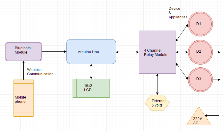
The proposed system has two main parts hardware and software. The hardware part consists of three main hardware components smartphone, Arduino board and Bluetooth module. Software part consist of Arduino integrated development environment and Bluetooth terminal smartphone application which is used for wireless communication between smartphone and Arduino board. Since we are controlling AC appliances, we will require a Relay module as well because AC appliances work on a much higher voltage and cannot be directly controlled by the Arduino UNO development board . Ensure that the maximum voltage and current ratings of the appliance being controlled are well within the range of the rated voltage and current of the relay module. The IoT is one of the leading and advantageous technologies in the 21st century, which can give the high level implementation feasibility in the field of wireless telecommunications.
DIY home automation using Arduino, Relay and Bluetooth Module(HC-
If this value is matching then Arduino sends operating voltage to the relay module. Home Automation Using Arduino and Bluetooth is an IoT project to control our home appliances like light, fan, cooler, etc. from a Smartphone. In this project, we use Arduino Uno and HC-05 Bluetooth Module and we give the command from our smartphone. To add Bluetooth functionality, we will use the HC-05 Bluetooth module.

If you have any queries in the post you can ask us in the comment section. We also sell projects in our Projects section on the homepage. Moreover, set the value of the pins connected with the three bulbs to HIGH by using digitalWrite() function. Specify the pin as the first parameter and the value as the second parameter. Configure the pins connected with the bulbs and the TX pin as output pins and the RX pin as an input pin. Specify the pin as the first parameter and the mode as the second parameter.
Of technologies influence us to use smartphones to remotely control the home appliances. An automated devices has ability to work with versatility, diligence and with lowest error rate. The idea of home automation system is a significant issue for Researchers and home appliances companies. Automation system not only helps to decrease the human labor but it also saves time and energy.
Some pins are used to send to 16×2 LCD and some are command pins. In other words, every pin has a role in controlling a single pixel on the display.16 x 2 LCD has sixteen columns and two rows. That means, it can display sixteen characters per row and it has two such rows. After complete the App setup/configuration, now we need to identify the load values of the App button. The app transmits Different load values when different buttons are pressed. When we will press a button on the app, the app sends a particular Load value to the Arduino through the Bluetooth module.
The IoT can also be defined as a smart and interconnected network in a highly dynamic infrastructure. The biggest deal in IoT is to collect the huge data and data security in maintaining the data confidentiality and providing the privacy for every entity. As a result of all these aspects, new difficulties are entering in improving and implementing the current technologies.

This will help us to communicate with other Bluetooth devices such as your smartphone and exchange messages between your smartphone and the Arduino UNO development board. Inside the infinite loop() we first check if serial data is available in the buffer. If data is found then the characters are added one by one to the array ‘inSerial’ using a while loop. Then we will call the Check_Protocol() function with ‘inSerial’ as an argument inside it. This function will be responsible for controlling the bulbs by comparing the received data and the command in the application.


No comments:
Post a Comment